樓主年紀輕輕,就有經天緯地之才,定國安邦之智,古人云,臥龍鳳雛得一而安天下,而今,天祐我大中華,滄海桑田5000年,中華神州平地一聲雷,飛沙走石,大舞迷天,朦朧中,只見頂天立地一金甲天神立於天地間,這人英雄手持雙斧,二目如電,一斧下去,混沌初開,二斧下去,女媧造人,三斧下去,小生傾倒.得此大英雄,實耐之幸也,民之福也,怎不叫人喜極而泣.......古人有少年樓主說為證,少年之樓主如紅日初升,其道大光;河出伏流,一瀉汪洋;潛龍騰淵,鱗爪飛揚;乳虎嘯谷,百獸震惶;鷹隼試翼,風塵吸張;奇花初胎,皇皇;干將發硎,有作其芒;天戴其蒼,地履其黃;縱有千古,橫有八荒;小生對樓主之仰慕如滔滔江水連綿不絕,海枯石爛,天崩地裂,永不變心.
看完樓主的帖子,我的心情竟是久久不能平靜。正如老子所云:大音希聲,大象無形。我現在終於明白我缺乏的是什麼了,正是樓主那種對真理的執著追求和樓主那種對理想的艱苦實踐所產生的厚重感。面對樓主的帖子,我震驚得幾乎不能動彈了,樓主那種裂紙欲出的大手筆,竟使我忍不住一次次地翻開樓主的帖子,每看一次,讚賞之情就激長數分,我總在想,是否有神靈活在它靈秀的外表下,以至能使人三月不知肉味,使人有餘音繞樑、三日不 絕的感受。樓主,你寫得實在是太好了。我惟一能做的,就只有把這個帖子頂上去這件事了。
樓主的帖子實在是寫得太好了。文筆流暢,修辭得體,深得魏晉諸朝遺風,更將唐風宋骨發揚得入木三分,能在有生之年看見樓主的這個帖子。實在是我三生之幸啊。看完樓主的這個帖子之後,我竟產生出一種無以名之的悲痛感——啊,這麼好的帖子,如果將來我再也看不到了,那我該怎麼辦?那我該怎麼辦?直到我毫不猶豫地把樓主的這個帖子收藏了,我內心的那種激動才逐漸平靜下來。可是我立刻想到,這麼好的帖子,倘若別人看不到,那麼不是浪費樓主的心血嗎?經過痛苦的思想鬥爭,我終於下定決心,犧牲小我,奉獻大我。我要拿出這帖子奉獻給世人賞閱,我要把這個帖子一直往上頂,往上頂!頂到所有人都看到為止!
在遇到你之前,我對人世間是否有真正的聖人是懷疑的;而現在,我終於相信了!我曾經忘情於兩漢的歌賦,我曾經驚訝於李杜的詩才,我曾經流連於宋元的詞曲。但現在,我才知道我有多麼淺薄!
樓主,你的高尚情操太讓人感動了。在現在這樣一個物慾橫流的金錢社會裡,竟然還能見到樓主這樣的性情中人,無疑是我這輩子最大的幸運。讓我深深感受到了人性的偉大。樓主 的帖子,就好比黑暗中刺裂夜空的閃電,又好比撕開烏雲的陽光,一瞬間就讓我如飲甘露,讓我明白了永恆的真理在這個世界上是真實存在著的。只有樓主這樣具備廣闊胸懷和完整知識體系的人,才能作為這真理的惟一引言者。看了樓主的帖子,我陷入了嚴肅的思考中。我認為,如果不把樓主的帖子頂上去,就是對真理的一種背叛,就是對謬論的極大妥協。因此,我決定義無返顧地頂了!

mcfeng 發表在 痞客邦 留言(0) 人氣()

作者:徐業良(2002-07-17),推薦:徐業良(2002-07-17)


附註:本文發表於汽車購買指南雜誌,2002年八月號,史丹福專欄。


淺談汽車結構設計

mcfeng 發表在 痞客邦 留言(0) 人氣()

作者:徐業良(2002-07-17),推薦:徐業良(2002-07-17)


附註:本文發表於汽車購買指南雜誌,2002年八月號,史丹福專欄。


淺談汽車結構設計

mcfeng 發表在 痞客邦 留言(0) 人氣()

3. Pressure measurements  

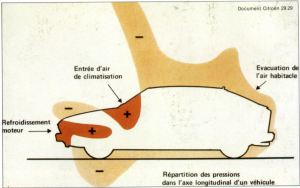
These measurements help to provide a partial solution to the problems of engine cooling and passenger cabin air-conditioning.

Pressures are expressed as a non-dimensional coefficient independent of speed:

Cp = P-Po
1/2 V2

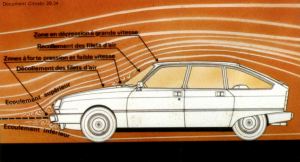
Bernouilli's equation : 1/2 pV2 + P = Constant along an air fillet is valid as a first approximation for the front of the vehicle. It proves that high-pressure areas have low air speed. Conversely, where the air fillets cling to the body, there is a depression. (The drawing will help you to understand this relation between air speeds and pressures at any point).

Pressure measurements make it possible to trace isobars (lines perpendicular to the air fillets visualising the lines along which pressure remains equal at a given value) on the vehicle's form.

The choice of the position of the air inlet for passenger-cabin air-conditioning will lie in the pressure zone at the foot of the windscreen.

Air-fillet flow over a Citoën GSA

AN AIR OF ECONOMY  

The power that the engine must develop in order to overcome different forms of resistance (apart from accelerations and gravity) is represented by the formula:

W wheels  = N. Wm = 1/2QCxSV3 +f. M.V.

where:

  • W wheels = power on driving wheels

  • N = transmission efficiency

  • Wm = power on engine output shaft

  • Q = air density

  • S = frontal area of car

  • Cx = coefficient of drag

  • f = frictional coefficient

  • M = vehicle mass

  • V = vehicle speed

  • 1/2 CxSV3 = aerodynamic resistance

  • f.M.V. = running resistance

The two following graphs represent respectively the formulae above, applied to a current standard production car, and the car's consumption in litres per 100 km according to speed. We can note the importance of streamlining for speeds approaching and over 90 km/h /56 mph), and the similarity between resistance and consumption curves, demonstrating the important role played by aerodynamics in fuel saving.

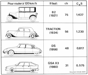
To travel at 120 kph (75 mph)

  • the B2 of 1921 with a CxS of 1,437 required 75 bhp

  • the Traction of 1934 with a CxS of 1,230 required 56 bhp

  • the DS of 1956 with a CxS of 0,817 required 48 bhp

  • while the GSA X3 of 1980 required only 31 bhp thanks to its very low CxS of 0,575.

When a car's CxS is improved by 10 %, consumption at 120 km/h (74.6 mph) goes down by 7 %, at 90 km/h (56 mph) by 5 %, in town traffic by 1 %.

The characteristics of motor cars' resistance to motion can be improved by entirely redesigning their bodywork.

The bodies of current 4-door saloons have Cxs coefficients lying between 0.575m2 (6.19 sq.ft) for the best and 0.900 m2 (9.69 sq.ft) for the least good, or CxS of between 0.32 and 0.48.

The improvement of known aerodynamic forms can also be achieved by fitting corrective adjuncts.

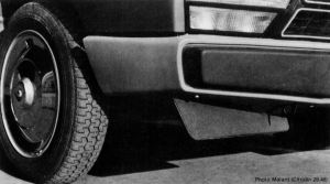
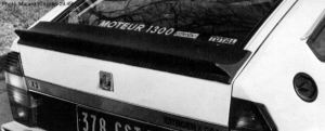
The drag of the Citroën GSA X3 has been reduced by the addition of a forward spoiler (which acts as a deflector and reduces the air-flow under the body) and of an aerofoil beneath the rear window (which reduces drag by modifying the rear lift characteristics), and by fitting a better streamlined rear-view mirror. The spoiler improves the CxS by 2.7 %, the aerofoil by 7.5 %. Both together improve the CxS by 10 % and reduce petrol consumption by 7.5 % at 120 km/h (74.6 mph).

And yet, if in the future every manufacturer is to be faced with achieving the best aerodynamic shapes, the results of these studies will always remain subordinate to sociological and legal possibilities (impossibility of producing extremely long, low cars, for instance), just as it will remain combined with the stylist's own trends.

In this respect, let us point out the misconception of which stylists, manufacturers, journalists and public alike are guilty about items such as spoilers and aerofoils, considered by one and all as optional extras for a sports car, whereas in fact, when, properly designed, they are first and foremost energy economisers which could easily and cheaply by provided for in standard production models.

Knowing that the shape of the body weighs heavily in the decision to buy a car, it is the stylists, at Citroën's, who combine the results of body studies with respect of the various restrictions they must comply with:

  1. volume restrictions regarding overall dimensions, inside spaciousness, the engine, location of the tank, the spare wheels and the boot.

  2. accessibility restrictions for the number of doors and visibility restrictions for the windows.

  3. standards for shock absorbers, head-lamps, rear lights, traffic indicators, number plates etc...

  4. restrictions connected with production, such as stamping and assembly problems with sheet metal whose nature imposes the shapes being cut up in various elements.

The aerodynamicist, for his part, has to check the results found with the first few shapes made up, and to suggest possible improvements to the stylist. The entire effectiveness of their collaboration takes form in their definition of an ambitious aerodynamic performance project and in their aptitude to achieve it in a seductive form.

This mode of collaboration between stylist and technician has been and remains characteristic of the genesis of Citroën models.

Long before the energy crisis was upon us, and by mere logic and a desire for a coherent approach to car-body design, Citroën models had already achieved exemplary CxS values recognised by specialists the world over.

These studies undertaken years ago now ensure for Citroën a far from negligible advance where the influence of "the right shape" on reducing fuel consumption is concerned.

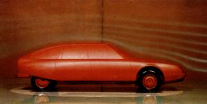
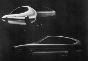
Below - one of the first -styling sketches for the CX

Aerodynamic co-efficient values for various Citroëns in standard road-going configuration

Model Cx S(m2) CxS(m2)
D Spécial 0,382 2,136 0,817
CX 0,369 1,924 0,709
Visa Super 0,391 1,731 0,677
LNA 0,392 1,700 0,667
SM 0,339 1,952 0,662
Visa Club 0,378 1,747 0,660
GS 1220 Club 0,361 1,809 0,653
GSA Club 0,345 1,809 0,624
GS X3 0,332 1,809 0,600
GSA X3 0,318 1,809 0,575


This article originally appeared in Double Chevron #59 © Automobiles Citroën 1980

© 1999 Julian Marsh

mcfeng 發表在 痞客邦 留言(0) 人氣()


3. Pressure measurements  


These measurements help to provide a partial solution to the problems of engine cooling and passenger cabin air-conditioning.


Pressures are expressed as a non-dimensional coefficient independent of speed:


Cp = P-Po
1/2 V2


Bernouilli's equation : 1/2 pV2 + P = Constant along an air fillet is valid as a first approximation for the front of the vehicle. It proves that high-pressure areas have low air speed. Conversely, where the air fillets cling to the body, there is a depression. (The drawing will help you to understand this relation between air speeds and pressures at any point).


Pressure measurements make it possible to trace isobars (lines perpendicular to the air fillets visualising the lines along which pressure remains equal at a given value) on the vehicle's form.


The choice of the position of the air inlet for passenger-cabin air-conditioning will lie in the pressure zone at the foot of the windscreen.


Air-fillet flow over a Citoën GSA


AN AIR OF ECONOMY  


The power that the engine must develop in order to overcome different forms of resistance (apart from accelerations and gravity) is represented by the formula:


W wheels  = N. Wm = 1/2QCxSV3 +f. M.V.


where:


  • W wheels = power on driving wheels


  • N = transmission efficiency


  • Wm = power on engine output shaft


  • Q = air density


  • S = frontal area of car


  • Cx = coefficient of drag


  • f = frictional coefficient


  • M = vehicle mass


  • V = vehicle speed


  • 1/2 CxSV3 = aerodynamic resistance


  • f.M.V. = running resistance


The two following graphs represent respectively the formulae above, applied to a current standard production car, and the car's consumption in litres per 100 km according to speed. We can note the importance of streamlining for speeds approaching and over 90 km/h /56 mph), and the similarity between resistance and consumption curves, demonstrating the important role played by aerodynamics in fuel saving.


To travel at 120 kph (75 mph)


  • the B2 of 1921 with a CxS of 1,437 required 75 bhp


  • the Traction of 1934 with a CxS of 1,230 required 56 bhp


  • the DS of 1956 with a CxS of 0,817 required 48 bhp


  • while the GSA X3 of 1980 required only 31 bhp thanks to its very low CxS of 0,575.


When a car's CxS is improved by 10 %, consumption at 120 km/h (74.6 mph) goes down by 7 %, at 90 km/h (56 mph) by 5 %, in town traffic by 1 %.


The characteristics of motor cars' resistance to motion can be improved by entirely redesigning their bodywork.


The bodies of current 4-door saloons have Cxs coefficients lying between 0.575m2 (6.19 sq.ft) for the best and 0.900 m2 (9.69 sq.ft) for the least good, or CxS of between 0.32 and 0.48.


The improvement of known aerodynamic forms can also be achieved by fitting corrective adjuncts.


The drag of the Citroën GSA X3 has been reduced by the addition of a forward spoiler (which acts as a deflector and reduces the air-flow under the body) and of an aerofoil beneath the rear window (which reduces drag by modifying the rear lift characteristics), and by fitting a better streamlined rear-view mirror. The spoiler improves the CxS by 2.7 %, the aerofoil by 7.5 %. Both together improve the CxS by 10 % and reduce petrol consumption by 7.5 % at 120 km/h (74.6 mph).


And yet, if in the future every manufacturer is to be faced with achieving the best aerodynamic shapes, the results of these studies will always remain subordinate to sociological and legal possibilities (impossibility of producing extremely long, low cars, for instance), just as it will remain combined with the stylist's own trends.


In this respect, let us point out the misconception of which stylists, manufacturers, journalists and public alike are guilty about items such as spoilers and aerofoils, considered by one and all as optional extras for a sports car, whereas in fact, when, properly designed, they are first and foremost energy economisers which could easily and cheaply by provided for in standard production models.


Knowing that the shape of the body weighs heavily in the decision to buy a car, it is the stylists, at Citroën's, who combine the results of body studies with respect of the various restrictions they must comply with:


  1. volume restrictions regarding overall dimensions, inside spaciousness, the engine, location of the tank, the spare wheels and the boot.


  2. accessibility restrictions for the number of doors and visibility restrictions for the windows.


  3. standards for shock absorbers, head-lamps, rear lights, traffic indicators, number plates etc...


  4. restrictions connected with production, such as stamping and assembly problems with sheet metal whose nature imposes the shapes being cut up in various elements.


The aerodynamicist, for his part, has to check the results found with the first few shapes made up, and to suggest possible improvements to the stylist. The entire effectiveness of their collaboration takes form in their definition of an ambitious aerodynamic performance project and in their aptitude to achieve it in a seductive form.


This mode of collaboration between stylist and technician has been and remains characteristic of the genesis of Citroën models.


Long before the energy crisis was upon us, and by mere logic and a desire for a coherent approach to car-body design, Citroën models had already achieved exemplary CxS values recognised by specialists the world over.


These studies undertaken years ago now ensure for Citroën a far from negligible advance where the influence of "the right shape" on reducing fuel consumption is concerned.


Below - one of the first -styling sketches for the CX


Aerodynamic co-efficient values for various Citroëns in standard road-going configuration


ModelCxS(m2)CxS(m2)
D Spécial0,3822,1360,817
CX0,3691,9240,709
Visa Super0,3911,7310,677
LNA0,3921,7000,667
SM0,3391,9520,662
Visa Club0,3781,7470,660
GS 1220 Club0,3611,8090,653
GSA Club0,3451,8090,624
GS X30,3321,8090,600
GSA X30,3181,8090,575


This article originally appeared in Double Chevron #59 © Automobiles Citroën 1980

© 1999 Julian Marsh


mcfeng 發表在 痞客邦 留言(0) 人氣()


AERODYNAMICS


Citroën has long been recognised as one of the leaders in the field of aerodynamics - forced on them by a fiscal policy in France which penalised large capacity engines.  In order to achieve both good performance and economy with relatively small capacity engines, there was a very real need to investigate means of reducing air resistance.


In 1980, with the introduction of the GSA, Citroën were building the most aerodynamic 5 door saloon on the market.  Audi matched the 0,31 Cx of this car with the much larger 4 door Audi 100 - it is much easier to achieve good aerodynamic results with a large vehicle than with a small one.


Aerodynamics is all the rage. Many a motor manufacturer in search of fuel economy is now discovering this science, which is also an art.


As was the case for the "traction avant" - or front wheel drive car, this is one of the fields in which Citroën has been disporting for many years. Followed today by many others.


During the year 1979, the German magazine "Stern" wind tunnel tested ten cars - and noted the GS's aerodynamic superiority.


A year later, the newspaper "Die Welt" remarked that the lines of the "cars of the future" currently elaborated by stylists have in fact been in existence since 1974: they are those of the Citroën CX , the car with the apt name (the Cx of a car is its coefficient of penetration through the air). Other observers noted that such and such so-called experimental models, French or foreign, intended for the years 1982-85, are still far from reaching the Cx of the standard production Citroën GSA X3. A German Consumer Association wrote to Citroën precisely to cast doubts on the real value of this model's CX. The marque thereupon provided all the proofs:


The Cx of the GSA X3, as measured at the Aerotechnical Institute at Saint-Cyr l'Ecole, with two occupants (310 lbs) and 130 lbs of luggage aboard, with the engine running to maintain a normal road clea-rance, is in fact 0.318. The Consumer Association took cognisance of this and naïvely admitted: "The specialists who advised us were of the opinion that such a sensational value was practically unattainable". Yet it is the best Cx in the world for a standard production car. Thanks for recognising the fact!


All over the World, the Cx battle rages, with penetration coefficients as its weapons. Hardly have they been discovered when attempts are already under way to manipulate them. It is now useful to take stock: what is aerodynamics to-day?


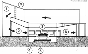
Diagram of the wind tunnel at the St-Cyr Aerotechnical Institute, used by all French motor-car manufacturers:


  1. stabilisation chamber 


  2. injet  


  3. test tunnel  


  4. roller bench  


  5. aero-dynamometer  


  6. central diffuser  


  7. lateral diffusers  


  8. motor fan unit 


  9. refrigeration exchanger


THE SCIENCE OF THE WIND  


Aerodynamics is an experimental science whose aim is the study of the relative motions of a solid body with regard to the surrounding air. Its application to the design of a car body constitutes one of the chief lines of the quest for energy economy in motor vehicles.


In order to move over the ground, a body must overcome two forces:


  • resistance to tyre tread motion, which is dependent on the state of the surfaces in contact and proportional to the vehicle's mass. The slower the vehicle moves, the greater its effect.


  • resistance to forward motion, which depends on the shape of the body and on its frontal area. The higher the speed, the greater its effect.


All this leads one to see in motor-car aerodynamic research a means of reconciling economy and comfort while respecting the imperatives of safety.


In the XVIth century, the first, measurements of air resistance were carried out on freely falling bodies, and it was only at the end of the XIXth century that a new method appeared: submitting the body to be studied to an artificial air stream. It is on this principle that wind tunnels work. 


The initial means of ventilating wind tunnels was compressed air, then the fan, first used as a blower, and later (as is now the case) for suction. In 1909, the well- known engineer Eiffel added two essential devices: an intake and a diffuser. This type of wind-chamber is the prototype of all present day tunnels.


In applications of motor car aerodynamics, the cross section of the experimental chamber is of the order of 15 to 20 m2 (160 to 215 sq. ft.), i.e. 10 to 20 times the vehicle's cross-section. In the main stream, wind speed reaches 100 mph with a stability of  ±1% in experimental time and space.


This homogeneity is fundamental, as is a low ground-limit layer (dead fluid zone).


Automotive aerodynamics also relies on reduced scale wind tunnels for use with models, the scale usually being 1/5. These preliminary shape-research trials, quicker and less costly than full-scale ones, eliminate gross errors on the first prototypes.


Wind-tunnels are fitted with relatively complex dynamometric devices allowing measurement of all aerodynamic forces. The car-dynamometer system forms a unit which can be turned through a certain angle relative to the wind, thus allowing the simulation of side wind.


It should however be borne in mind that there is no universal standard for these measurements. Each wind tunnel itself constitutes the standard for the experimental research done there. From one wind tunnel to another, there may be dynamometric or blown-wind dispersions provoking slight distortions between the results found with one or another tunnel.  For this reason, it is always well to know where and in what circumstances the measurements put forward were made.


It is, in particular, important to know whether the results stated were obtained with a full-scale car, rather than with a 1/5 scale model (whose aerodynamic results are generally about 20% better), but also whether the car was a real one, and loaded.


BALANCE OF FORCES AND AIR FILLETS  


Aerodynamic research as regards motor cars is done experimentally by measuring forces and pressures and by visualising the air stream with fillets.


1. Measurement of forces 


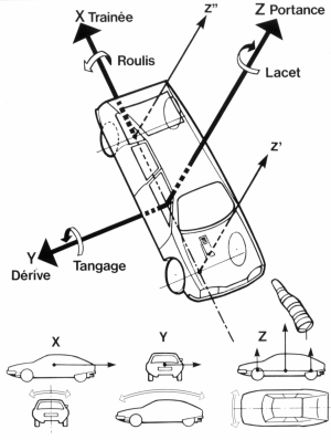
A car in a wind is subjected to 3 forces (drag, drift and lift) and 3 moments (force multiplied by leverage) which are roll, pitch and yaw, related to the trihedral XYZ.


The diagram shows the axes of measurement of the forces and moments (force x leverage) applied to a vehicle (Citroën CX) when it is running. Force X is known as Drag, and its moment as Roll. Force Y is Drift and its moment Pitch. Force Z is Lift (broken down into forward Lift and rear Lift), and its moment is Yaw.


Where energy saving is concerned, drag, also known as resistance to the vehicle's motion, is alone involved. The aim is to reduce it as much as possible.


All the other components play a role in the vehicle's stability and more especially in its sensitiveness to gusty side winds.


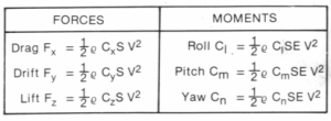
Forces and moments depend on the square of the wind's velocity (i.e., in current practice, of vehicle speed) according to the following formulae:


Axes of measurement for the forces and moments applied to a Citroën CX


  • Trainée = Drag Roulis = Roll


  • Dérive = Drift Tangage = Pitch


  • Portance = Lift Lacet = Yaw


where:


  • P = air density


  • V = wind velocity in tunnel


  • S = frontal area of vehicle


  • E = wheelbase


  • Cx = coefficient of drag 


  • Cy = coefficient of drift 


  • Cz = coefficient of lift


  • Cl = coefficient of roll


  • Cm = coefficient of pitch 


  • Cn = coefficient of yaw


It can be seen that the resistance to a vehicle's motion of Drag Fx varies with air density and speed, but also with its CxS (coefficient of drag multiplied by frontal vehicle area), and not merely with its more usually quoted CX alone.


Example: with a Cx definitely less good than that of the CX (0.39 against 0.36) but a smaller frontal area (1.70 m2 = 18.3 sq. ft against 1.92m2 = 20.7 sq. ft) the aerodynamic coefficient of the LNA is better (0.66, as against 0.71 for the CX). 


It should be noted that, in aerodynamics, the coefficients are non-dimensional and that Cy and Cz have no absolute physical significance; the frontal area S is retained for a force Fy acting on the lateral surface of the vehicle (profile).


All coefficients Cx Cy Cz Cl Cm Cn are read in the wind tunnel for various angles of side-slip ß (angle between the axis of the vehicle on test and the axis of the wind tunnel).


Running at 80.8 mph with a 25 mph side wind is simulated in a wind tunnel by an 84.5 mph wind and an angle of 17 degrees between the model and the wind.


Vo = 84.5 mph (136 km/h)


Vl = 25 mph (40 km/h)


Vv = 80.8 mph (130 km/h)


ß = 17 degrees


Knowing the distribution of weights and lifts on the front and rear axles, it becomes possible to calculate the weight taken off the wheels at all vehicle speeds with different side winds.


For instance, for a standard vehicle with a total weight of 2 640 lbs (1760 lbs forward, 880 lbs rear), the weight taken off  the front axles may be 1 000 N (216 lbs) at 93.6 mph with a 50 mpg side wind, whereas a racing car may have a weight lift equivalent to the axle load.


Using forces and moments, it becomes easy, by simple computation, to define the position of the centre of lateral thrust in relation to the centre of gravity. Together with lift, this is one of the criteria of road stability.


2 Visualisation of air fillets 


Visualisation of air-flow is indispensable to the comprehension and analysis of the results founded. Two methods are in current use:


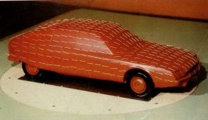
  • Visualisation of air fillets with strands of wool stuck to the vehicle  


  • Visualisation by means of smoke produced by one or more movable jets.  


The study of air-flow patterns makes it possible, among other things, to look for means of compensating any aerodynamic effects which might oppose the operation of certain components of the car. Nothing is ever simple! Thus the (highly desirable) improvement of a vehicle's coefficient of drag may prove detrimental to the cooling of the braking system (highly regrettable).


This is why, during wind tunnel tests, the temperature of various braking-system parts is monitored. The visualisation of air fillets then makes it possible to design practical means of air supply to ensure the indispensable cooling of disc brakes.


Example: the aerodynamic study of the Citroën CX led to the setting up of an elaborate braking system: ventilated front brakes, sheet-steel deflectors forcing the air towards the braking system on the pivot, air guides fixed on the under-part of the front of the body.


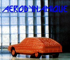
Visualisation of air fillets in a wind tunnel by means of strands of wool attached to a 1/5 scale model of a CX


Visualisation of air fillets in a wind tunnel by means of coloured smoke on a 1/5 scale model of a CX


3. Pressure measurements  


These measurements help to provide a partial solution to the problems of engine cooling and passenger cabin air-conditioning.


Pressures are expressed as a non-dimensional coefficient independent of speed:


Cp = P-Po
1/2 V2


Bernouilli's equation : 1/2 pV2 + P = Constant along an air fillet is valid as a first approximation for the front of the vehicle. It proves that high-pressure areas have low air speed. Conversely, where the air fillets cling to the body, there is a depression. (The drawing will help you to understand this relation between air speeds and pressures at any point). 


Pressure measurements make it possible to trace isobars (lines perpendicular to the air fillets visualising the lines along which pressure remains equal at a given value) on the vehicle's form.


The choice of the position of the air inlet for passenger-cabin air-conditioning will lie in the pressure zone at the foot of the windscreen.


mcfeng 發表在 痞客邦 留言(0) 人氣()

AERODYNAMICS

Citroën has long been recognised as one of the leaders in the field of aerodynamics - forced on them by a fiscal policy in France which penalised large capacity engines.  In order to achieve both good performance and economy with relatively small capacity engines, there was a very real need to investigate means of reducing air resistance.

In 1980, with the introduction of the GSA, Citroën were building the most aerodynamic 5 door saloon on the market.  Audi matched the 0,31 Cx of this car with the much larger 4 door Audi 100 - it is much easier to achieve good aerodynamic results with a large vehicle than with a small one.

Aerodynamics is all the rage. Many a motor manufacturer in search of fuel economy is now discovering this science, which is also an art.

As was the case for the "traction avant" - or front wheel drive car, this is one of the fields in which Citroën has been disporting for many years. Followed today by many others.

During the year 1979, the German magazine "Stern" wind tunnel tested ten cars - and noted the GS's aerodynamic superiority.

A year later, the newspaper "Die Welt" remarked that the lines of the "cars of the future" currently elaborated by stylists have in fact been in existence since 1974: they are those of the Citroën CX , the car with the apt name (the Cx of a car is its coefficient of penetration through the air). Other observers noted that such and such so-called experimental models, French or foreign, intended for the years 1982-85, are still far from reaching the Cx of the standard production Citroën GSA X3. A German Consumer Association wrote to Citroën precisely to cast doubts on the real value of this model's CX. The marque thereupon provided all the proofs:

The Cx of the GSA X3, as measured at the Aerotechnical Institute at Saint-Cyr l'Ecole, with two occupants (310 lbs) and 130 lbs of luggage aboard, with the engine running to maintain a normal road clea-rance, is in fact 0.318. The Consumer Association took cognisance of this and naïvely admitted: "The specialists who advised us were of the opinion that such a sensational value was practically unattainable". Yet it is the best Cx in the world for a standard production car. Thanks for recognising the fact!

All over the World, the Cx battle rages, with penetration coefficients as its weapons. Hardly have they been discovered when attempts are already under way to manipulate them. It is now useful to take stock: what is aerodynamics to-day?

Diagram of the wind tunnel at the St-Cyr Aerotechnical Institute, used by all French motor-car manufacturers:

  1. stabilisation chamber 

  2. injet  

  3. test tunnel  

  4. roller bench  

  5. aero-dynamometer  

  6. central diffuser  

  7. lateral diffusers  

  8. motor fan unit 

  9. refrigeration exchanger

THE SCIENCE OF THE WIND  

Aerodynamics is an experimental science whose aim is the study of the relative motions of a solid body with regard to the surrounding air. Its application to the design of a car body constitutes one of the chief lines of the quest for energy economy in motor vehicles.

In order to move over the ground, a body must overcome two forces:

  • resistance to tyre tread motion, which is dependent on the state of the surfaces in contact and proportional to the vehicle's mass. The slower the vehicle moves, the greater its effect.

  • resistance to forward motion, which depends on the shape of the body and on its frontal area. The higher the speed, the greater its effect.

All this leads one to see in motor-car aerodynamic research a means of reconciling economy and comfort while respecting the imperatives of safety.

In the XVIth century, the first, measurements of air resistance were carried out on freely falling bodies, and it was only at the end of the XIXth century that a new method appeared: submitting the body to be studied to an artificial air stream. It is on this principle that wind tunnels work. 

The initial means of ventilating wind tunnels was compressed air, then the fan, first used as a blower, and later (as is now the case) for suction. In 1909, the well- known engineer Eiffel added two essential devices: an intake and a diffuser. This type of wind-chamber is the prototype of all present day tunnels.

In applications of motor car aerodynamics, the cross section of the experimental chamber is of the order of 15 to 20 m2 (160 to 215 sq. ft.), i.e. 10 to 20 times the vehicle's cross-section. In the main stream, wind speed reaches 100 mph with a stability of  ±1% in experimental time and space.

This homogeneity is fundamental, as is a low ground-limit layer (dead fluid zone).

Automotive aerodynamics also relies on reduced scale wind tunnels for use with models, the scale usually being 1/5. These preliminary shape-research trials, quicker and less costly than full-scale ones, eliminate gross errors on the first prototypes.

Wind-tunnels are fitted with relatively complex dynamometric devices allowing measurement of all aerodynamic forces. The car-dynamometer system forms a unit which can be turned through a certain angle relative to the wind, thus allowing the simulation of side wind.

It should however be borne in mind that there is no universal standard for these measurements. Each wind tunnel itself constitutes the standard for the experimental research done there. From one wind tunnel to another, there may be dynamometric or blown-wind dispersions provoking slight distortions between the results found with one or another tunnel.  For this reason, it is always well to know where and in what circumstances the measurements put forward were made.

It is, in particular, important to know whether the results stated were obtained with a full-scale car, rather than with a 1/5 scale model (whose aerodynamic results are generally about 20% better), but also whether the car was a real one, and loaded.

BALANCE OF FORCES AND AIR FILLETS  

Aerodynamic research as regards motor cars is done experimentally by measuring forces and pressures and by visualising the air stream with fillets.


1. Measurement of forces 

A car in a wind is subjected to 3 forces (drag, drift and lift) and 3 moments (force multiplied by leverage) which are roll, pitch and yaw, related to the trihedral XYZ.

The diagram shows the axes of measurement of the forces and moments (force x leverage) applied to a vehicle (Citroën CX) when it is running. Force X is known as Drag, and its moment as Roll. Force Y is Drift and its moment Pitch. Force Z is Lift (broken down into forward Lift and rear Lift), and its moment is Yaw.

Where energy saving is concerned, drag, also known as resistance to the vehicle's motion, is alone involved. The aim is to reduce it as much as possible.

All the other components play a role in the vehicle's stability and more especially in its sensitiveness to gusty side winds.

Forces and moments depend on the square of the wind's velocity (i.e., in current practice, of vehicle speed) according to the following formulae:


Axes of measurement for the forces and moments applied to a Citroën CX

  • Trainée = Drag Roulis = Roll

  • Dérive = Drift Tangage = Pitch

  • Portance = Lift Lacet = Yaw

where:

  • P = air density

  • V = wind velocity in tunnel

  • S = frontal area of vehicle

  • E = wheelbase

  • Cx = coefficient of drag 

  • Cy = coefficient of drift 

  • Cz = coefficient of lift

  • Cl = coefficient of roll

  • Cm = coefficient of pitch 

  • Cn = coefficient of yaw

It can be seen that the resistance to a vehicle's motion of Drag Fx varies with air density and speed, but also with its CxS (coefficient of drag multiplied by frontal vehicle area), and not merely with its more usually quoted CX alone.

Example: with a Cx definitely less good than that of the CX (0.39 against 0.36) but a smaller frontal area (1.70 m2 = 18.3 sq. ft against 1.92m2 = 20.7 sq. ft) the aerodynamic coefficient of the LNA is better (0.66, as against 0.71 for the CX). 

It should be noted that, in aerodynamics, the coefficients are non-dimensional and that Cy and Cz have no absolute physical significance; the frontal area S is retained for a force Fy acting on the lateral surface of the vehicle (profile).

All coefficients Cx Cy Cz Cl Cm Cn are read in the wind tunnel for various angles of side-slip ß (angle between the axis of the vehicle on test and the axis of the wind tunnel).

Running at 80.8 mph with a 25 mph side wind is simulated in a wind tunnel by an 84.5 mph wind and an angle of 17 degrees between the model and the wind.

Vo = 84.5 mph (136 km/h)

Vl = 25 mph (40 km/h)

Vv = 80.8 mph (130 km/h)

ß = 17 degrees

Knowing the distribution of weights and lifts on the front and rear axles, it becomes possible to calculate the weight taken off the wheels at all vehicle speeds with different side winds.

For instance, for a standard vehicle with a total weight of 2 640 lbs (1760 lbs forward, 880 lbs rear), the weight taken off  the front axles may be 1 000 N (216 lbs) at 93.6 mph with a 50 mpg side wind, whereas a racing car may have a weight lift equivalent to the axle load.

Using forces and moments, it becomes easy, by simple computation, to define the position of the centre of lateral thrust in relation to the centre of gravity. Together with lift, this is one of the criteria of road stability.

2 Visualisation of air fillets 

Visualisation of air-flow is indispensable to the comprehension and analysis of the results founded. Two methods are in current use:

  • Visualisation of air fillets with strands of wool stuck to the vehicle  

  • Visualisation by means of smoke produced by one or more movable jets.  

The study of air-flow patterns makes it possible, among other things, to look for means of compensating any aerodynamic effects which might oppose the operation of certain components of the car. Nothing is ever simple! Thus the (highly desirable) improvement of a vehicle's coefficient of drag may prove detrimental to the cooling of the braking system (highly regrettable).

This is why, during wind tunnel tests, the temperature of various braking-system parts is monitored. The visualisation of air fillets then makes it possible to design practical means of air supply to ensure the indispensable cooling of disc brakes.

Example: the aerodynamic study of the Citroën CX led to the setting up of an elaborate braking system: ventilated front brakes, sheet-steel deflectors forcing the air towards the braking system on the pivot, air guides fixed on the under-part of the front of the body.

Visualisation of air fillets in a wind tunnel by means of strands of wool attached to a 1/5 scale model of a CX

Visualisation of air fillets in a wind tunnel by means of coloured smoke on a 1/5 scale model of a CX

3. Pressure measurements  

These measurements help to provide a partial solution to the problems of engine cooling and passenger cabin air-conditioning.

Pressures are expressed as a non-dimensional coefficient independent of speed:

Cp = P-Po
1/2 V2

Bernouilli's equation : 1/2 pV2 + P = Constant along an air fillet is valid as a first approximation for the front of the vehicle. It proves that high-pressure areas have low air speed. Conversely, where the air fillets cling to the body, there is a depression. (The drawing will help you to understand this relation between air speeds and pressures at any point). 

Pressure measurements make it possible to trace isobars (lines perpendicular to the air fillets visualising the lines along which pressure remains equal at a given value) on the vehicle's form.

The choice of the position of the air inlet for passenger-cabin air-conditioning will lie in the pressure zone at the foot of the windscreen.

mcfeng 發表在 痞客邦 留言(0) 人氣()

      空氣力學(Aerodynamics)


由於下壓力的大小將直接影響到高速行駛的操控和
穩定性,因此大多數強調高性能的跑車在空力設計
上也多半著墨於下壓力的確保。


「空力」是F1賽事中經常出現的名詞,不過除了賽車之外,空力性能的優劣與否,其實也會影響到你我所駕駛的一般市售車輛。簡單的說,空力也就是物體置於氣流中所承受的力。以汽車為例,一部在行駛狀態下的汽車所必須承受的空力共可有六種,即前後、上下、左右以及前後軸、左右軸和垂直軸所衍生出的六分力。不過一般則是以前後方向的風阻係數(Cd)和左右方向的下壓力/上揚力(Cl)較為常見。


藉由額外裝設的外觀套件來改變空力特性,早已成
為時下高性能跑車在外型設計上的常見手法。


風阻係數主要取決於車輛的正面投影面積,因此如機翼般流線的造型,其風阻係數必然越低;下壓力/上揚力則是指車輛所承受來自上下兩方向的力。風阻係數和下壓力/上揚力有著密不可分的關連性,一般來說風阻係數愈大,下壓力也就相形增大,因此早期的房車基於靜肅性和節能考量,外型多半會採用低風阻係數的設計。相對的,基於安全和穩定性的考量,跑車的外型則多半會著眼於下壓力,因此風阻係數也會較房車來得略高。
不過近年來隨著汽車科技日新月異,風阻係數和下壓力已幾乎能藉由空力套件來獲得平衡,Ferrari聞名於世的超級跑車Enzo,就能夠利用空力套件的變化而在不影響風阻係數的條件下增大下壓力。

mcfeng 發表在 痞客邦 留言(2) 人氣()

      空氣力學(Aerodynamics)   
由於下壓力的大小將直接影響到高速行駛的操控和
穩定性,因此大多數強調高性能的跑車在空力設計
上也多半著墨於下壓力的確保。

「空力」是F1賽事中經常出現的名詞,不過除了賽車之外,空力性能的優劣與否,其實也會影響到你我所駕駛的一般市售車輛。簡單的說,空力也就是物體置於氣流中所承受的力。以汽車為例,一部在行駛狀態下的汽車所必須承受的空力共可有六種,即前後、上下、左右以及前後軸、左右軸和垂直軸所衍生出的六分力。不過一般則是以前後方向的風阻係數(Cd)和左右方向的下壓力/上揚力(Cl)較為常見。 
藉由額外裝設的外觀套件來改變空力特性,早已成
為時下高性能跑車在外型設計上的常見手法。

風阻係數主要取決於車輛的正面投影面積,因此如機翼般流線的造型,其風阻係數必然越低;下壓力/上揚力則是指車輛所承受來自上下兩方向的力。風阻係數和下壓力/上揚力有著密不可分的關連性,一般來說風阻係數愈大,下壓力也就相形增大,因此早期的房車基於靜肅性和節能考量,外型多半會採用低風阻係數的設計。相對的,基於安全和穩定性的考量,跑車的外型則多半會著眼於下壓力,因此風阻係數也會較房車來得略高。不過近年來隨著汽車科技日新月異,風阻係數和下壓力已幾乎能藉由空力套件來獲得平衡,Ferrari聞名於世的超級跑車Enzo,就能夠利用空力套件的變化而在不影響風阻係數的條件下增大下壓力。

mcfeng 發表在 痞客邦 留言(0) 人氣()


無言...

mcfeng 發表在 痞客邦 留言(0) 人氣()


無言...

mcfeng 發表在 痞客邦 留言(0) 人氣()


2006年式 VW GOLF R32 がベースの RISE & AXIS デモカーです。
ALPIL製 カーボンエアロで外装を極め、NEX車高調で足回りをかためたオールブラックのの外装は
純正風ですが、カーオーディオはRISEのテクノロジーを究極に突き詰めたド級の物です☆
BEWITH A-110S 物ブロックアンプを6台 ☆ 容積30リッターの特別製バスレフエンクロージャーは

mcfeng 發表在 痞客邦 留言(1) 人氣()

Blog Stats
⚠️

成人內容提醒

本部落格內容僅限年滿十八歲者瀏覽。
若您未滿十八歲,請立即離開。

已滿十八歲者,亦請勿將內容提供給未成年人士。